
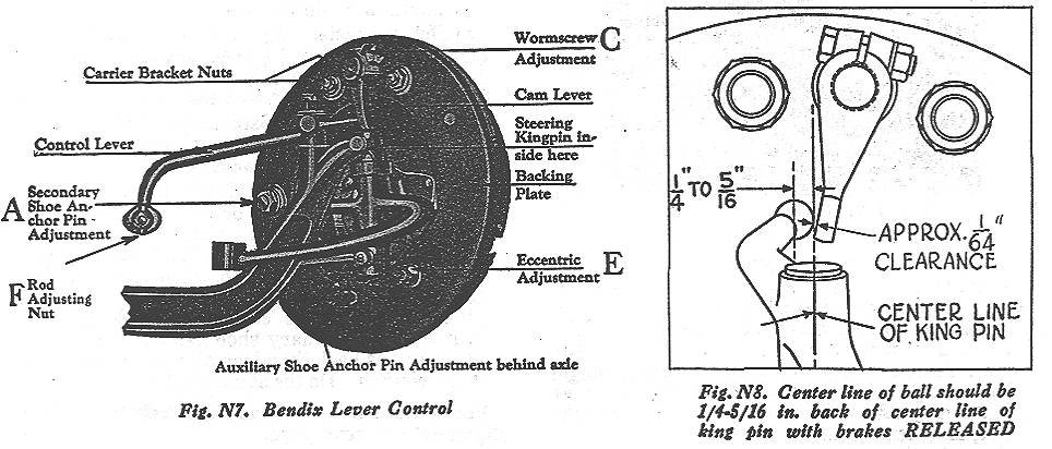
In the Bendix lever control, the brake cam is actuated by a control lever attached to the axle of the vehicle. One end of this control lever is ball shaped and bears against a small lever attached to the camshaft, as shown in Fig. N7. The other end of the control is operated by the brake pull rod. This provides a very simple means of actuating the front brakes without interfering with the movement of the wheels in steering. When the wheels are turned, the flat end of the small lever slides over the ball and the relationship between the two remains approximately the same.
As adjusted at the factory, the center of the ball is about 1/4 to 5/16 in. behind the center of the steering king pin, when the brakes are released. As the brake lining wears, the center of the ball moves slightly forward. Any serious variation from these dimensions will cause the brake to be applied when the car turns a corner. With the ball ends in the correct position the outer brake is released when the car is turning a corner.
Minor Adjustment for Clearance
Minor or lining clearance adjustment is made as follows:
- With all wheels jacked up turn the square ball nuts F on ends of pull rods until center line of ball on operating lever is 1/4 in. to 5/16 in. back of the center line of the steering king pin, with brakes in released position. See Figs. N7 and N8.
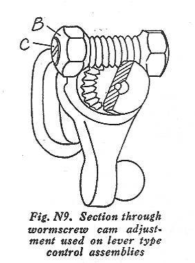
- Next loosen lock nut on the operating cam worm screw C and turn slotted screw to the right until brake shoes are free. See Fig. N7 and Fig. N9.
- Loosen eccentric adjustment lock nut E (Fig. N7) and then turn eccentric adjustment screw in same direction as wheel revolves when car moves forward, until shoes are tight against drum. Now back off gradually on this adjusting screw until wheel just turns freely. Hold eccentric adjusting screw and tighten locknut.
- Now turn the operating cam wormscrew (“C” Fig. N7) to the left until wheel binds, then back off until wheel just turns freely. Tighten locknut. Do the same to the other front wheel.
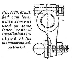
Note: On later designs the operating cam adjustment is incorporated in the end of the cam lever itself, as shown in Fig. N10.
Rear Wheels
Adjust rear brakes (where Bendix equipped) in same manner as outlined for the fronts, except that cam operating lever should stand at 65 degrees (see Fig. N19), or just less than perpendicular, brakes applied. To change angle of rear brake lever, back off on pull rod ball nut and clamping bolt and move lever backward or forward on its serrations as shown in Fig. N21.
Equalizing
Equalize as follows: Apply brakes by use of pedal depressor until the tightest wheel can be turned by hand. Slack off on ball nut of tight wheel a turn at a time until all four are the same, remembering that where a flexing single cross-shaft is involved a change in the rear brake may affect the front brake on the same side and vice-versa. Remove depressor tool from pedal and try all four wheels for drag. There should be no drag if previous operations were done properly.
Major Adjustments at Anchors
Anchor pins should be adjusted: (a) when fitting new lined shoes; (b) when anchor pin nuts are found loose; (c) when other adjustments fail to give satisfactory results.
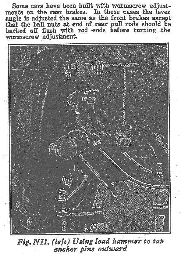
To adjust anchors: Turn eccentric adjustment (see Fig. N7) away from articulating pin and leave loose. Slacken off on anchor pin nuts (Fig. N11), then tap both anchors out toward edge of drum, as in Fig. N11. Hold brake on tight by 100-pound load on the end of a 10-in. length monkey wrench applied to control lever. Tap anchor pins on end and try to turn wheel forward with brake applied. Still holding brake on, tighten both nuts as tight as possible with a 16-in. wrench. Release brake and readjust clearances as outlined in paragraphs 1 to 7 inclusive.
Drum Ports, Important
Drums with inspection ports permit a far more satisfactory adjustment as follows:
- Slack off eccentric adjustment and slightly loosen both anchors. Apply brake by hand and tap anchor nuts, Fig. N21a.
- Using a feeler, adjust upper anchor to give .005 in. clearance at the heel (anchored) end of the secondary shoe and lower anchor to get .005 in. clearance at heel of auxiliary shoe.
- Using a feeler, adjust eccentric to get .010 in. clearance at toe end (end that is hinged to primary shoe) of secondary shoe.
- Now insert .010 in. feeler blade in drum hole and, while turning drum, check clearance over remaining length of primary and auxiliary shoe lining. The clearance should be approximately uniform full length. If not, balance by tapping carrier bracket slightly one way or the other. Recheck all clearances, making sure that toe of secondary shoe has twice as much clearance as heel, then lock all anchors with 16-24 inch wrench. Do the same to all four wheels.
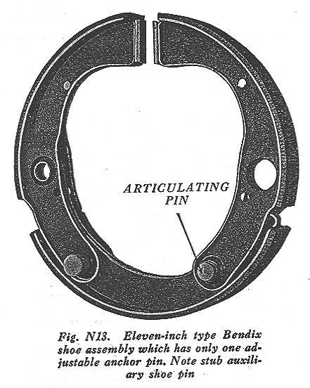
Adjustment of Single Anchor Pins on 11-inch Bendix Brake
On the cam and plate type eleven-inch diameter brake there is only one adjustable anchor pin. This is the secondary anchor pin, the auxiliary pin stopping short of the backing plate and not being attached thereto. In this case the auxiliary pin forms an articulating joint between the secondary and auxiliary shoes. Shoe anchor pin construction of the eleven-inch brake is shown in Figs. N7 and N13.
To adjust the secondary anchor pin on this type of assembly, proceed as follows:
- Loosen anchor nut A (Fig. N7) about one turn. Do the same to other 3 wheels.
- Turn eccentric adjustment (Fig. N7) away from articulating pin (by turning it in opposite direction to that in which wheel revolves when car moves forward) until wheel spins freely. Do the same to other 3 wheels.
- Spin the wheel rapidly or drive the car in a forward direction and apply the brake with considerable force. While the brake is still applied, tap each anchor pin on its end and outwardly not less than three times, with a lead hammer to assist its movement.
- Tighten the 4 anchor nuts firmly with a 16 inch wrench and readjust eccentric at each brake.
If Bendix brakes do not give satisfactory performance after making these adjustments, check carrier brackets and operating cams, as outlined below.
Adjustment of Operating Cams and Their Carrier Brackets
Adjustment of the brake operating cams and their carrier brackets should be made whenever the shoe assemblies are removed and also on all major adjustments. The carrier bracket may be considered in correct adjustment when it is bolted to the backing plate tightly enough to resist movement by hand but loose enough to be readily moved when tapped with a hammer. Examine and make sure that the plain washer is not bent. Make sure that the lock washer is not broken.
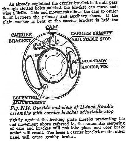
On some models a special cam shaped stop is fitted to control the position of the carrier bracket. This construction is shown in Fig. N14. To adjust this type proceed as follows:
- Turn each stop away from bracket.
- Drive car a short distance and apply brakes violently.
- Turn stops until they touch bracket, back off slightly and tighten. This should give about 1/32 inch clearance between stop and bracket. The carrier bracket nuts on this type of construction should have the same tightness as those without the stop.
Lever Control Type, Also Used on the Following Cars
| Durant 1928 Erskine to 1930 Studebaker Dictator (some) Studebaker President 8 (some) Oldsmobile 6 prior to F30 Pierce-Arrow (8 Cyl) | Hupmobile 6 (1926-1927) Marmon 68, 78 Essex to 1929 Studebaker Commander (some) Falcon Knight Star 4 and 6 |