
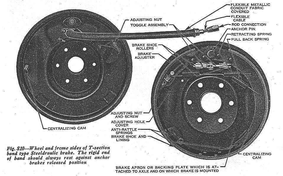
1. Place the hand brake lever in the fully released position. Make sure that foot brake pedal is against its stop in the fully released position and that it clears underside of floorboards by 3/8 in. If possible block the pedal in place by inserting a block of wood between under side of pedal pad and upper face of floorboards.
Anchor Adjustment
2. Turn each drum until inspection port is aligned with brake anchor. With a narrow feeler gage test the clearance between edge of anchor “G” and end of adjuster “F”, Fig. S11. This clearance should be not less than 1/32 (.032) in. and not more than 1/16 (.064) in. Test each wheel in this manner. The clearance should be the same at each wheel (within limits of about .005 in.), but if it isn’t, adjust to uniformity by shortening or lengthening the pull rods as shown in Fig. S9. If these adjustments are properly executed the pedal will return smartly to its stop when applied and released and it will have no backlash. If pedal does not return smartly look for misaligned cross-shaft or broken return springs, or lack of lubrication.
Centralizing the Bands
3. Turn wheel until drum inspection hole is directly over the shoe centralizer which, on T section models, is located 1/4 of a turn around from the anchor pin on rigid side of band. The centralizer on T section models is usually a cam “C” as shown in Figs. S7 and S9. On the older channel shoe models it is in the form of a “butterfly” cam as shown at “7” in Fig. S2. Some few of the 11-inch models with T section shoes utilize a sliding type centralizer comprising a coil spring and bolt, mounted in an elongated hole in the backing plate, as shown in Fig. S8. Loosen centralizer locknut; then insert a .020 or .025 in. feeler blade between lining and drum at centralizer as shown in Fig. S12. Now turn centralizer until feeler is just gripped. Tighten centralizer locknut. On 11 inch models with the sliding type centralizer as shown in Fig. S8, insert the feeler at a point about midway of the length of the rigid portion of the band. If properly centered the band should have about .005 to .010 in. more clearance at the flexible side than on the rigid side. Do this on the other three brakes.

Equalizing
4. Jack up all four wheels or place car on testing machine, then using a depressor set the pedal to a position approximately the middle of its total travel. Remove adjusting hole cover plates from each of the 4 backing plates.
5. On the later models with T-Section bands adjust the lining clearance by turning the knurled adjusting nut, Figs. S10 and S13, until wheel has a heavy drag. Do the same to the other three brakes.
On the older models with channel section bands adjust the lining clearance by unlocking clip 4, Fig. S2, and turning adjuster screw 3 until wheel has a heavy drag. Do the same to the other three brakes. Set to desired front to rear ratio by reducing or increasing drag on front or rear pair of brakes.
6. Now release the pedal and test each wheel for drag. If none of the wheels drag, check for equalization on machine or road and loosen the tight brake at clearance adjustments mentioned in paragraph 5. After easing off on the tight brake run road wheel or car backwards with brake applied. This will force the adjuster to its seat on band.
It should be remembered that for best results the pedal should travel 2 or more inches before brakes take hold. This free travel (not to be confused with backlash) permits each toggle to assume the angle where it produces greatest leverage and softest pedal action.
7. If brakes are unsatisfactory after making all of the foregoing adjustments and especially if they have a hard pedal (require too much pedal pressure) check centralization of band assembly in the up and down direction. The anchor end of the rigid part of band and the lower end of rigid part of band should have approximately the same clearance. If the up and down clearance is not the same within .020 in., remove the band and relocate it with respect to the anchor as outlined under “High Pedal Pressure With Chatter”.
Drums
Makers of the Steeldraulic brake state that under no circumstances should the drums be turned down to correct an out of round condition. The most important requirement is that any foreign particles imbedded in the lining be removed.
Cautions for Steeldraulic Brakes
- When making anchor adjustment be careful not to unwind cables which will occur if same are allowed to turn.
- If no jig is available install lining in two pieces. If band is much distorted buy a new one.
- Don’t use a high coefficient lining to get softer pedal. Brake will tend to lock up if used.
- Never adjust to less than .020 lining clearance.
Used on the Following Cars
Auburn 1931 and 1932, 8 Cyl.
Hupmobile after 1927
Pontiac 1928 to 1932
Nash after 1929 (some)
De Vaux
Durant 1930, 1931
Oakland 1928 to 1932
Dodge 4 and Standard